2026 / Project
DC & AC Electric Drive Control
Reproducible MATLAB/Simulink studies of DC motor control and induction-motor indirect field-oriented control.
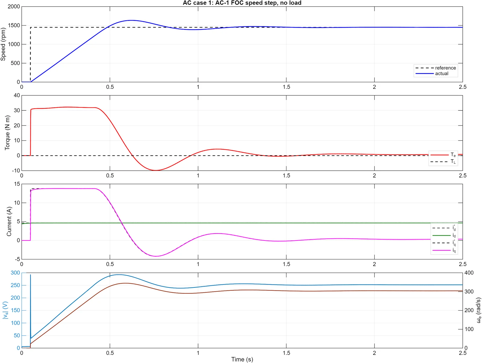
This project studies closed-loop speed and torque control for an armature-controlled DC motor and a three-phase squirrel-cage induction motor using indirect field-oriented control.
I built authoritative models in MATLAB R2025b and Simulink, using cascaded speed and current PI control for the DC drive and indirect field-oriented control for the induction motor.
What the models leave out
Simscape Electrical wasn’t available, so the converter and inverter stages are averaged voltage models with saturation limits. That is enough to study how the controllers respond to speed steps, load changes and torque commands, inside modelled current limits with anti-windup. It leaves out switching effects such as dead time and semiconductor losses.
A separate SciPy calculation in the repository checks the DC speed-step result against the MATLAB export. That check compares final speed; it doesn’t check the whole transient or the induction-motor model, and none of this establishes hardware performance.
Reproducible experiment set
Six cases cover no-load speed steps, load-torque disturbance rejection, and torque or current-command tracking for both machines. Each run exports time histories, plots, and metrics including rise time, settling time, overshoot, steady-state error, peak current, torque ripple, and recovery behavior.
The repository keeps model generation, simulation scripts, generated .slx files, CSV outputs, figures, and the LaTeX report together. One command rebuilds the models and evidence, making the report a reproducible engineering artifact rather than a collection of manually copied screenshots.
Results
| Case | Command | Rise (s) | Settling (s) | Overshoot | Peak current |
|---|---|---|---|---|---|
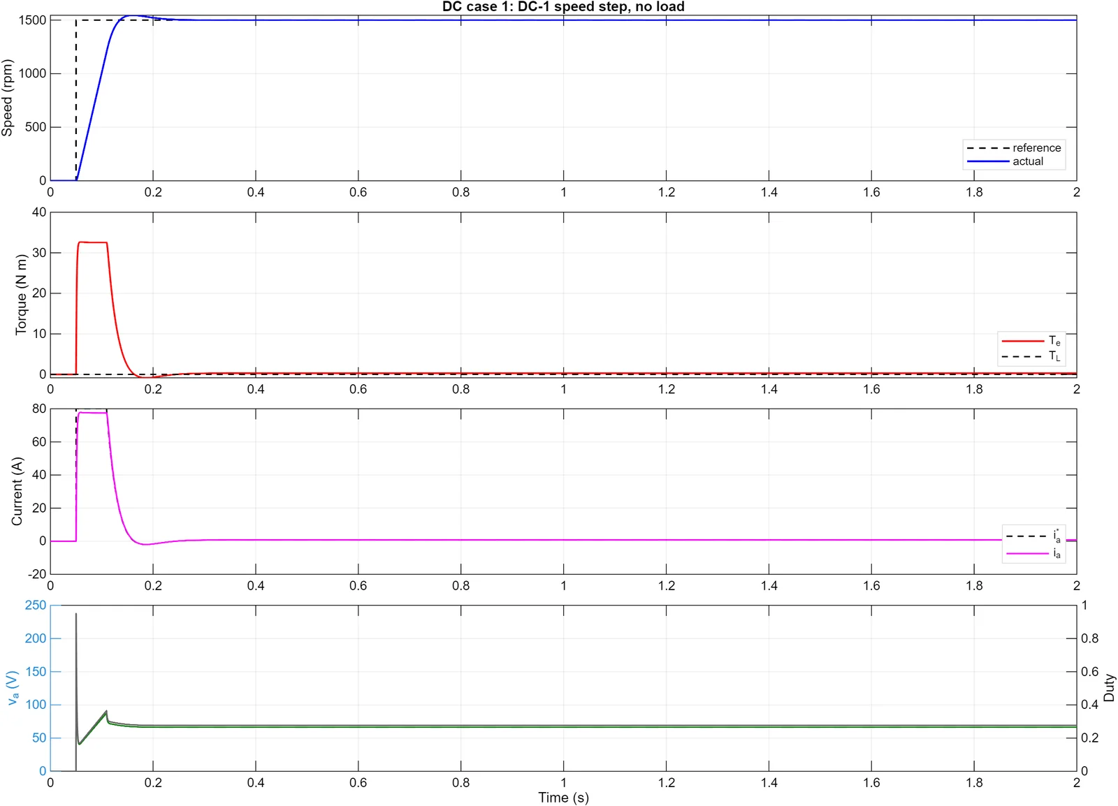
| DC speed step | 1500 rpm | 0.059 | 0.139 | 3.0% | 77.8 A |
| DC load step (8 N·m) | 1500 rpm | 0.059 | 0.808 | 3.0% | 77.8 A |
| Induction motor speed step | 1500 rpm | 0.343 | 1.05 | 12.7% | 14.6 A |
| Induction motor load step (9 N·m) | 1500 rpm | 0.343 | 1.43 | 12.7% | 14.6 A |
The DC drive reaches its current limit while accelerating, then backs off as the back EMF rises, and settles in 0.14 s with essentially no speed error. The induction motor is slower because the controller has to hold rotor flux while staying inside the inverter’s voltage and current limits. In both load tests the speed returns to 1500 rpm with negligible error. The torque-tracking cases are judged from the plots rather than a single overshoot number, because each command has several levels and a reversal.
Related work
All projectsCase study: Human-reviewed AI document workflows
How I built AI tools that read operational documents while keeping a person responsible for every record that matters. A two-minute read.
View project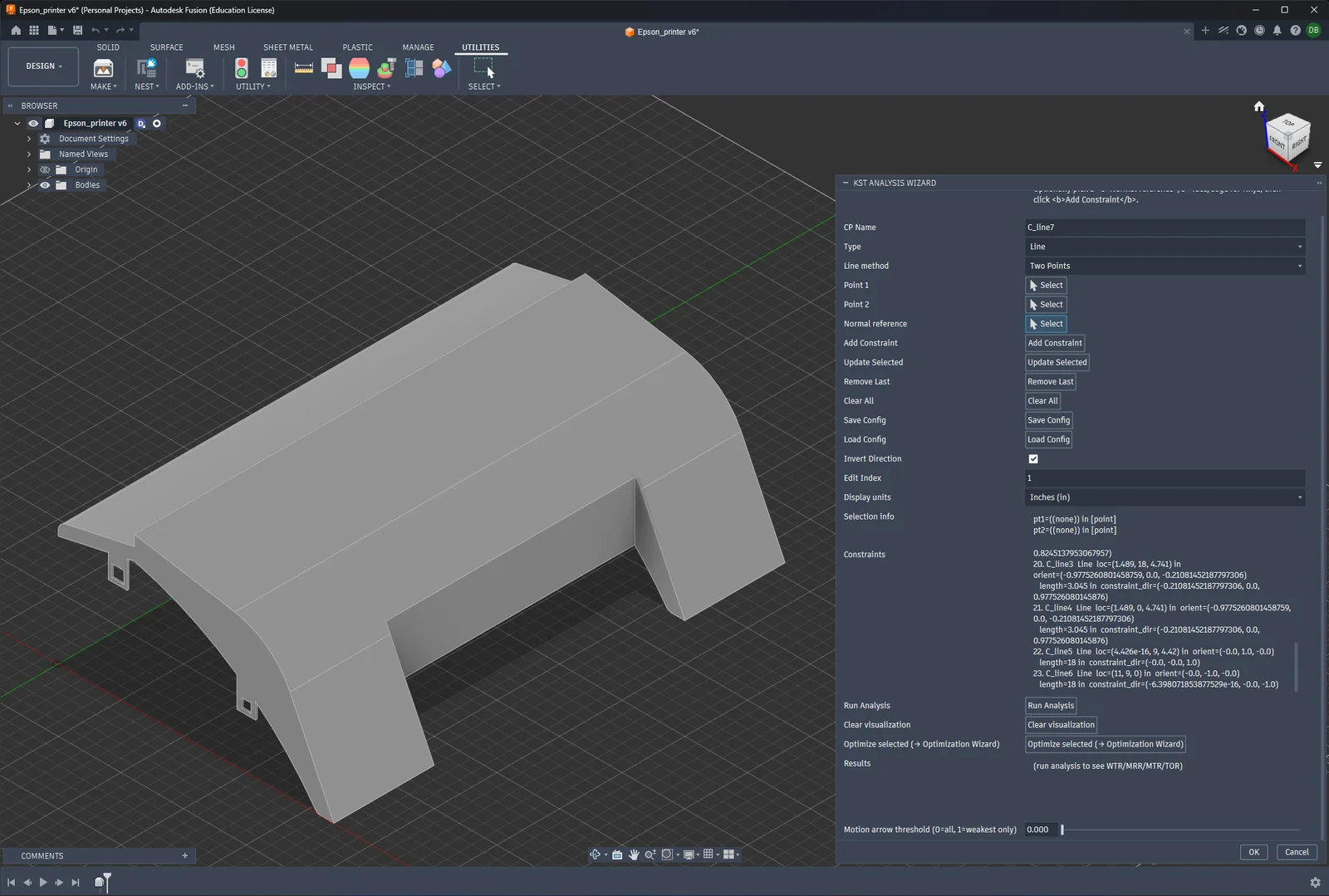
CAD-Integrated KST Assembly Rating Tool
A verified Python and Fusion 360 workflow for analyzing how assembly features constrain rigid-body motion.
View project